Overview
The Input/Output IC's that I use on the below
boards are either DS2406 (Single Input or Output only)
or DS2406P Dual I/O either I/O bit can be input or
output. This is a surface mount device located under the
PCB.
Current Projects
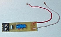
 Non Powered Input
I deem a non powered input, to be an input from the
real world that relies solely on the 1Wire interface for
power. I prefer not to use these style of interfaces
because the actual 1wire interface can only deliver so
much power before the network communications start to
suffer, i.e. errors and unreliable operation.
I only use this style of interface in areas where space
is at a premium, i.e. within a PIR movement sensor. The
board requires a voltage free set of contacts.

 Powered Input
This style of input does not draw any extra power
from the 1wire interface other than what is required by
the IC itself, i.e. the pull-up resistor for the switch
is derived from the 12V Power supply, plus it also has
onboard visual indication of the input state (LED). The
board requires a voltage free set of contacts.

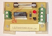
 Relay Output Board
This board provides a set of relay contacts rated at
240VAC 5A. I don't know that I would trust having this
kind of Voltage and current so close to my 1Wire
interface.

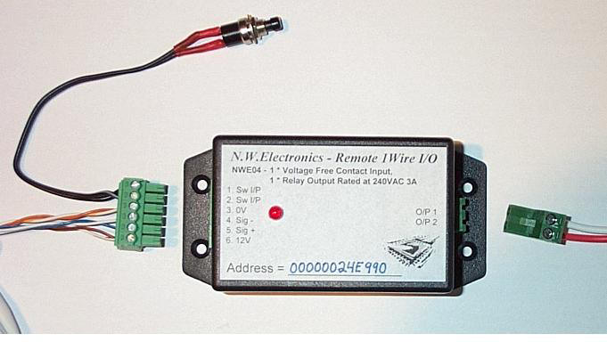
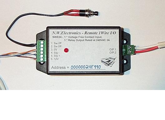
 Powered Input & Relay Output
Board
I thought the above relay output board was a bit
crude for general use around the place so I developed
the below unit. I think this looks better. This unit has
the same output characteristics as the above relay board
i.e. 240VAC @ 5A and it also has a voltage free set of
input contacts. I use the below modules in places like
the pool pump control. Under normal circumstances the
pump is controlled by MisterHouse through appropriate
timers based on the time of the year i.e. summer 2 hours
in the morning, three hours in the afternoon. Pressing
the switch reverses the pumps current state i.e. turns
the pump ON if it is currently OFF. I have also used
these in places such as bathroom movement sensor and
light control instead of two separate boards as per
above (Non powered input and a Relay output board).

There is
a RED Led to indicate when the output has been turned
ON.
 |